

Many semiconductor devices, such as FPGAs, require multiple power supplies.
It is required to follow the power supply sequence, so the discharge function of the power on / off control pin and output capacitor may be needed.
Here are some notes on the power supply sequence for FPGA and a useful sequence IC.
Check before sequence
Before considering the power supply sequence, it is important to check the slew rate of the output voltage of the power supply IC or module.
The power supply sequence must be observed in order to suppress the rush current at the time of power-on. However, when the slew rate of the output voltage of the power supply IC is steep, the rush current becomes large.
Some of the recent switching regulators have built-in soft start capabilities, which can reduce peripheral parts and simplify circuit.
Since the switching regulator with built-in soft start cannot control the slew rate, the rush current becomes large and the voltage does not increase monotonously. Therefore, it is necessary to confirm that there is no problem.
However, in the case of FPGAs, DSPs, etc., where a large number of capacitors are arranged in order to improve the response performance to the load fluctuation, the rush current at the time of power startup may become large.

Figure 1 : Non-Monotonically Increasing Startup Waveform Image
Definition of the power supply sequence
Once the slew rate of power output of the power source can be confirmed, it is then a confirmation of the power supply sequence.
The startup sequence of the FPGA is determined by grouping multiple power supply lines, such as Group A first, Group B second, and so on.
Figure 2 shows the power sequence required by the Intel® FPGA Stratix® V.
If you do not follow this sequence order, the rush current flows largely and affects the reliability.。
It is necessary to turn off the power in the reverse order of the start-up.
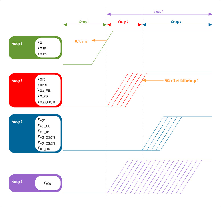
Figure 2 : StratixV power sequence
Tracking function
The output voltage of the grouped power source rises simultaneously by using the tracking function,.
In general, the slew rate of the rise voltage differs depending on the type of the power supply IC or module.
As a result, even if the signals to start the power supply are the same, the rise of the output voltage becomes uneven.
By using the tracking function, it is possible to raise and lower the voltage at the same slew rate as shown in Fig. 3, even if power supplies with different slew rates are used.
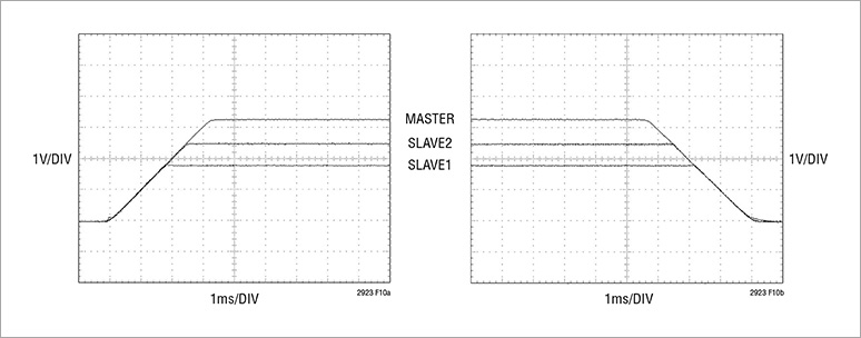
Figure 3:Tracking control waveform
Analog Devices’ LTC2923 is an IC that enables tracking control.
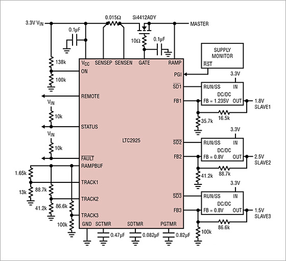
Figure 4:LTC2923 circuit diagram
Sequence control
Since FPGAs require multiple power supplies, designing sequence control with resistors and capacitors is very complex.
It is possible to control the sequence freely by using a microcomputer. However, when software development is required or 12V is supplied as the main power source, it is necessary to design a circuit that supplies power only to the microcomputer first, which complicates the hardware design.
In addition, modern FPGAs and DSPs require an off sequence, so that the off sequence cannot be controlled by resistor capacitor control, so a solution for sequence control is needed.
Analog Devices’ PSM(Power System Management)
For the FPGA power sequence, Analog Devices’ PSM Series product LTC2977 is recommended.
The PSM product does not require software development like a microcomputer. The power supply sequence can be easily customized by changing the register setting of the internal EEPROM through the GUI as shown in Fig. 5.
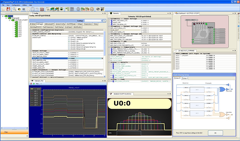
Figure 5:GUI of PSM
The operating voltage range of the LTC 2977 is 15V, and the 12V power supply used for industrial equipment can be directly input, so it is not necessary to have a power supply circuit controlled separately from the FPGA like a microcomputer.
This allows a simple circuit configuration of the power-on / off sequence required by the FPGA.
| Back to Technical Articles |
| Contact us |