

Electronic circuit breaker with current detection amplifier

What are the benefits of electronic circuit breakers?
If the power supply is short - circuited due to a circuit failure or operation error, an overcurrent flows, which leads to a secondary failure of the power supply. In addition, heat generated from the circuit components can cause an accident such as a fire. For this reason, many power supplies have a protective function such as a current limiting function, but I think there are many cases where a fuse is inserted to improve reliability.
However, the fuse may be blown by the rush current when the power is turned on if the error of the blowing current is large and there is no margin. Also, once it has melted, it needs to be replaced, which makes maintenance troublesome.
By using an electronic circuit breaker, the protection current can be set to the correct value, and it can be made maintenance free because it returns when the power supply is turned on again.
Current sense amplifier LT6118 for a wide range of power supply systems
The LT6118 is a high - side current sense amplifier with built - in power - on reset, reference and comparator, and can be used for industrial and automotive applications because its operation is regulated at -40 ℃ to 125 ℃.
It can operate from 2.7 V and has a maximum rating of 60 V for a wide range of power systems.
LT6118 features and functional block diagram are shown below.

LT6118 Functional Block Diagram from LT6118 Datasheet
LT6118 Features
Circuit example and results using LTspice
Below is an example of a circuit using LT6118 with LTspice. If the voltage exceeds about 3A at 48 V, the circuit is cut off by P-MOSFET (Q1).
The 500 uF capacitor in the output is used to confirm that the output is not cut off by the rush current during power - on, and does not need to be actually used in the circuit.
The current flowing through the output load is detected by the shunt resistor R2 and is output to OutA. This current is applied to the R3 and R9 resistors the voltage generated through the resistance of R3 and R9 is compared with the internal 400 mV peak to detect overcurrent.
The Zener diode D2 connected to the OoutC is for suppressing and protecting the Vgs of the N-MOSFET of the M1, and the Zener diode of the D1 is also for limiting and protecting the Vds of the Q1.
The time constant of R10 and C2 provides a dead zone during power - on, preventing the circuit breaker from operating due to rush current caused by charging the bypass capacitor due to power-on.
For low power systems, such as 5V, D1 and D2 are no longer needed and R5 and R10 should be scaled to 1/10.
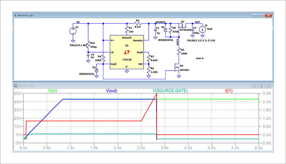
Circuit Example and Operating Waveform of 48 V Power Supply Circuit Breaker with LT6118