

Electronic circuit breaker with input overvoltage protection

What are the benefits of an electronic circuit breaker with input overvoltage protection?
In the case of the power supply of the receiving electronics connected to the power supply terminal, in addition to the protection by current limitation due to the failure of the load circuit, protection of overvoltage due to ringing and surge generated when the cable is connected may be required. This can be easily accomplished using LT4363.
Current Limited High Voltage Surge Stopper LT4363
The LT4363 is easy to use because it has an N-channel MOSFET driver, just like the LT1910 described in the related article "Self - Resetting Electronic Circuit Breakers". In addition, high-temperature products of -40℃ to 125℃ are available and can also be used for in-vehicle products.
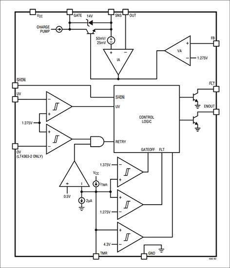
LT4363 features and functional block diagram are shown below.
LT1910 Functional Block Diagram from LT1910 Datasheet
LT 4363 Features
- surge resistance greater than 80 V at VCC clamp
- Wide operating voltage range : 4 V to 80 V
- Adjustable output clamp voltage
- Fast overcurrent limit : <5 µs
- Reverse input protection up to -60 V
- UV/OV comparator threshold can be adjusted
- Low power supply current at shutdown : 7μA
- Shutdown pins withstands voltages -60 V and 100 V
- Adjustable fault timer
- Controls the N - channel MOSFET
- Retry duty cycle during fault : <1% (LT4363-2)
- 12 - pin (4 mm x 3 mm) DFN package, 12 - pin MSOP package, or 16 - pin SO package
Circuit example and results using LTspice
Below is an example of the circuit of LT4363 using LTspice.
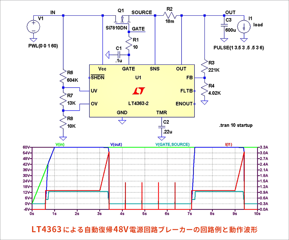
Automatic Recovery by LT4363 48 V Power Supply Circuit Breaker Circuit Example and Operation Waveform
The clamp voltage at overvoltage input is set by the voltage dividing resistor so that FB terminal becomes 1.275 V. Refer to the data sheet for clamp operation against overvoltage.
You can set the retry interval for the capacitor connected to the TMR terminal. Overcurrent detection can also be configured with the R2 shunt resistor.
Set the UV terminal to a level that prohibits operation at low voltage.
The OV terminal sets set to a level that prohibits retry in case of overvoltage fault. This is also effective in case of overcurrent. If the input voltage is set to IN, return by retry is prohibited, and when connected to GND, automatic return is always enabled.