

How to prevent device damage due to overvoltage

The main reason for destroying a device is to apply a voltage outside the specified range of the device.
From the standpoint of the reliability of systems shipped to the market, it is important to take measures, such as protective devices, on circuits to prevent devices from being destroyed by overvoltage.
How to prevent static damage?
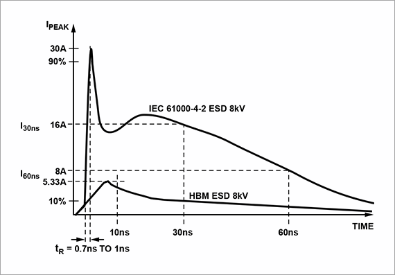
ESD damage due to static electricity is considered to be one of overvoltage damage.
In the case of static electricity, a very high voltage is applied in a short period of time (less than 1 ns), so an ESD suppressor / TVS diode is required as a protective element for ESD countermeasures. For example, you can use an ESD protection device from Ultra Electronics (available for purchase).
Since the interface is exposed to metal outside the housing, it is especially important to take measures against ESD.
Analog Devices has developed interface products with enhanced anti - ESD measures, and some of them meet the IEC 61000-4-2 level 3 standard.
Overvoltage breakdown due to noise
Overvoltage breakdown due to noise is caused by noise from the power supply source or noise generated between devices or between boards propagating through the power supply line or communication line and destroying devices.
Overvoltage noise may occur due to insertion or removal of the board or cable while the switch is on / off or hot.
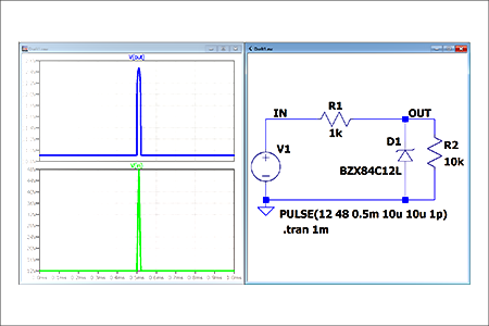
To prevent these overvoltage noises, the breakdown voltage of the Zener diode is used to clamp the overvoltage.
The figure below shows the simulation results using LTspice for clamp characteristics when 48 V overvoltage noise was applied to the Zener diode (BZX84C12L) of ON Semiconductor. As shown in the figure below, an overvoltage of 48 V is input. The above figure shows the simulation result of 48 V overvoltage noise being clamped to 12.5 V by the zener.
Overvoltage caused by inductive load or inductance
In systems where the power supply must be connected with a long cable, the inductance component of the cable can cause an overvoltage of 1m sec or on power - up. Under these conditions, the Zener diode used for noise reduction may consume more power than expected and exceed the allowable power.
In such cases, it is necessary to provide a stable power supply to the circuit by placing a high - voltage power supply IC or module between the power supply and the circuit.
However, in the case of power supply ICs and modules, the regulation function that outputs a stable voltage is required, so there is a limit to the operating voltage range that can be accommodated.
Examples of applications that meet these requirements include cameras, sensor modules, and in - vehicle for industrial equipment.
Overvoltage protection solution "Surge Stopper"
A surge stopper developed by Analog Devices Co., Ltd. can be used to prevent overvoltage of 1 msec or more, which is difficult to protect with TVS or Zener diodes. I looked up the word "surge" before I went into the content of the "surge stopper" product. I found out that it means "swell" or "big wave."
I had an image of surge = static electricity or noise, and I was wondering why it was over - voltage of 1 msec. If it meant "swell", I understood that it was a solution to stop over - voltage of 1 msec.
The MIL Standard specification (MIL-STD-1275D) states : You can see that the surge is required to respond to an overvoltage of 500 msec.
| Specification | Normal operation mode | Generator only mode |
|---|---|---|
| Steady state | 25V < VIN < 30V | 23V < VIN < 33V |
| Spike | Up to 250 V Energy = 15 mJ |
Same as normal operation mode |
| Surge | Up to 40 V, 500 ms RSOURCE = 20m Ω |
Up to 100 V, 500 ms RSOURCE = 500m Ω |
| Ripple | Size ±2 V | Size ±7 V |
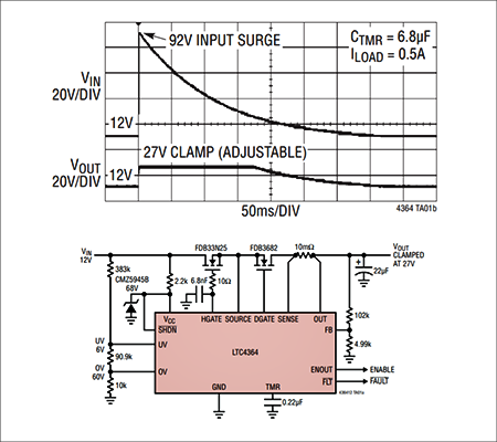
The diagram below shows the circuit diagram of the surge stopper product LTC4364 and the waveform when a 92 V surge is applied.
When a surge voltage is input to the 12 V line, the LTC4364 controls the FET (FDB33N25) to clamp to the voltage set by the voltage dividing resistor.
In the waveform shown below, the surge voltage of 92 V is clamped to 27 V. If the input voltage drops below the clamp setting voltage of 27 V, the output will also drop to match the input voltage.